Building Block 5 of 5
CAM Programming
Ask any shop manager: the best CAM programmers have machinist backgrounds. The true power of CAM starts with the operator’s knowledge and experience. Would you let a surgeon operate on you if you knew they had never studied anatomy?
-
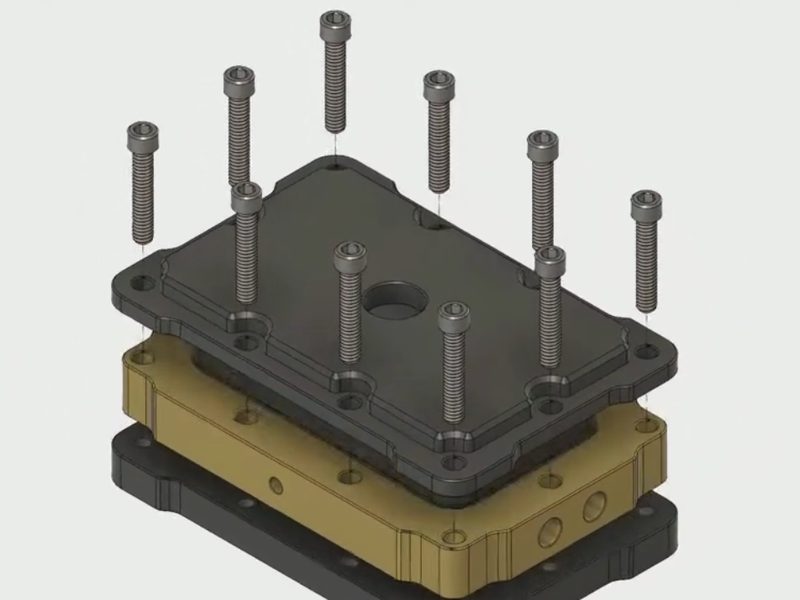
Mill certification project
-
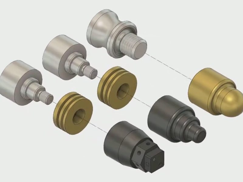
Lathe certification project


In the right hands, CAM systems like Mastercam and Fusion 360 are extremely productive tools. Rather than program with raw G code, CAM programs the machine graphically from a 3D mathematical model of your part — and the same model can generate programs for different machine controls. All projects and certification parts are offered in both systems to meet your preference, and project-based training includes 2D lathe and 3D mill.
A series of certification projects progressively adds part features, ending in two final assemblies — one mill, one lathe — of three parts each. They demonstrate the full range of features learned along the way, and completing one takes all five building blocks: work holding, tool selection, programming, setup, machine operation and inspection, to a specified fit and finish.
Putting it all together
The three parts must go together. That is why these are assemblies rather than six separate parts — it gives a student a go/no-go check they can run themselves. The parts either fit or they do not. It may create a learning experience and a lesson in rework.
All six are below, and they are the models from which a student programs. Click and rotate, pan or zoom — if 3D viewing is available.


Shown for viewing only. © Immersive Engineering, Inc.
Becoming the Total Machinist
A student finishing this building block has gone from no prior experience to programming from a model, with assessment at every stage and a Skills Learning Objective report showing exactly what they can do.
They also finish holding something. The certification assembly is a finished product a graduate can put in front of an employer and talk through — how it was programmed, how the machine was set and run, how it was inspected, and how they knew it was right. Walking an interviewer through that part evidences the core skills, the hand work and the G-code that got them there. One object, and it covers the whole pathway.